Nodes
A graph node (or procedure step) is the main unit of a procedure. A node, by default, is a procedure step. However, when grouped, it loses the status of a procedure step and becomes a part of a larger procedure step. The graph node always contains a set of enter actions (can be empty), a set of conditions, and a set of exit actions (can be empty).
Simple Node
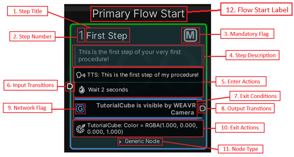
A simple graph node contains the following elements:
- Step Title — title of the node (or a procedure step). It supports multiple languages and can be modified from the Procedure Inspector.
- Step Number — number of the procedure step. It is generated automatically but can be modified further (applies only if the node is a procedure step).
- Mandatory Flag — indicates whether this node is mandatory or not. The user cannot skip a mandatory node. You can enable this toggle from Graph Editor or Procedure Inspector.
When a node is set to mandatory in an OpS procedure, the exit condition of that node automatically executes only when you click the Next button in the Game window.
- Step Description — description of the step. It supports multiple languages (applies only if the node is a procedure step).
- Enter Actions — set of actions to be executed when the node starts its playback.
- Input Transitions — point where transitions from other nodes are collected.
- Exit Conditions — list of exit conditions. Each exit condition is listed between the blue lines.
- Output Transitions — path to follow when the corresponding exit condition is evaluated to true.
- Network Flag — whether this condition will be shared among all players (in case of a multiplayer scene) or only for the local player.
- Exit Actions — actions to be executed when any of the exit conditions have been evaluated to true.
- Node Type — the type of your node.
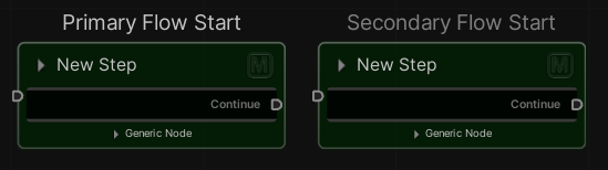
- Flow Start Label — indicates if the procedure starts with this node.
Note that the procedure can have multiple start nodes. You can have N Primary Flow Start nodes that are the main flows of the procedure, and N Secondary Flow nodes, which are flows that progress without affecting the manual progress of the procedure (next, previous step). To set a primary flow or a secondary flow start, right-click on the node and select Main\Secondary Flow.
Super Step
As mentioned above, the nodes can be grouped to form a so-called Super-Step. Put together, the nodes act as if they were a single Step composed of several phases (the nodes). To create a Super Step, right-click on the selected nodes and click Add Group.
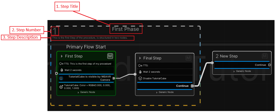
As any node, a Super Step has a title, a number and a description that can be edited.
- To add a node to an existing group — drag the node inside the group.
- To remove a node from a group — select the node, hold Shift, and drag the node outside of the group.
Hub Node
A hub node, as its name implies, waits for all the incoming transitions, and launches more execution flows in parallel.

No actions need to be taken for this node. In the figure above, the hub node waits for a transition (0 waited out of 1) and launches 3 execution flows in parallel. To create a Hub node, right-click on the graph and click on Create Hub Node.
The Hub Node inspector consists of a header and a body. The header contains the title of the node, while the body contains the number of input connections and links (both transition and node) to output transitions.
Event Node
It allows you to start another flow in the procedure when a Procedure event is triggered.
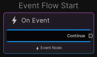
The Event Node inspector consists of a header and a body. The header contains the title of the node, while the body contains options about this node and enter\exit actions as well as Exit Conditions.
The options are:
- Manual Start — if disabled the event will be triggered at the start of the procedure, else you'll need to call it inside a procedure node.
- Auto Restart — the flow will be restarted at the end of the event flow.
- Execution Mode — whether this node will be used in the current execution mode or in a specific one.
- Execute Actions — how and when to execute the actions in this node.
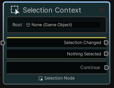
Selection Node
It allows you to define an object or a group of objects to be selected during a step of the procedure. You can define events that will be triggered after the selection is changed, or when nothing is selected.
The node must not be the first in the flow but must be preceded by another (empty or not).
The selection node inspector consists of three main sections: Options, Selection Items and Exit Condition. The last one is the classic exit condition inspector; the other parts are specific of this node.
The Options are:
- Selection Root — if the items that you want to select are parts of a "bigger" object (an engine for example), you should put the parent GameObject here.
- Stop on Exit — whether to stop the children flows when the exit condition is evaluated to true.
- Reset Selection — whether to reset the selection on exit.
- Apply on Start — whether to apply the selection logic when this node is reached or not.
- Can Take Notes — if enabled the user will be able to add\edit notes for this step.
- Execution Mode — whether this node will be used in the current execution mode or in a specific one.
The Selection Items section manages the items that you want to select or the events that will be triggered when something is selected or not.
Selection Changed Item Action
| Property | Function |
|---|---|
| Target Var | The variable in which you want to save your selection. |
| Async Mode | Enable this to make the flow asynchronous (i.e., start two different flows after the event). |
| Execute on Null Selection | Whether or not to perform selection changed actions even when nothing is selected. |
| Values | List of the object that you want to set when this event is triggered. |
Selection Null Item Action
| Property | Function |
|---|---|
| Stop Flow On Selection Changed | Stops this flow when the selection changes. |
| Values | List of the object that you want to set when this event is triggered. |
To add a new item to select, click on the Add Item button.
Add Item Action
| Property | Function |
|---|---|
| Target | The object that you want to select. |
| Selection Proxy | [Optional] If enabled and set, you can use this object as a proxy to select your target object. You need to add to your proxy object the Selection Proxy component. |
| Stop Flow On Selection Changed | Stops this flow when the selection changes. |
| Allow Deselection | Whether this object can be deselected. |
| Can Have Notes | When selecting this object, the user can take notes. |
| Values | List of the object that you want to set when this object is selected. |
Transitions
A Transition is a link between two Nodes. Transitions represent the navigation in the graph. You can add multiple actions to be executed when the transition path is followed.
To create the flow from one node to another, and set the execution order of the procedure, use transitions between nodes.
To make a transition: Click the output transition point of the node and then drag the line to the input transition point of the step to connect.
By changing the endpoints of the transition link, the actions related to the link will be lost.
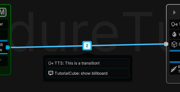
When a transition between nodes is valid, a preview of the transition is shown. Once a transition is established, it can be selected and loaded with actions if needed. If a transition is loaded with actions, a small "badge" is visible over the transition. The set of transition actions can be edited in the Procedure Inspector window.
The Transition inspector consists of a header and a body. Its header contains the buttons to reach the connecting nodes, while its body contains the list of actions to be executed when following the path of the transition.
- Execution Type — the way this transition will be executed: Always, Same Execution Flow, Only Once.